Anti-Islanding Protection with Grid-Tied PV Inverters
Anti-islanding protection is a commonly required safety feature which disables PV inverters when the grid enters an islanded condition. Anti-islanding protection is required for UL1741 / IEEE 1547. Knowledge of how this protection method works is essential for today’s PV system designers. We recently offered a webinar, featuring Eric Every, Sr. Applications Engineer, Yaskawa – Solectria Solar, who reviewed a variety of scenarios where anti-islanding protection would be necessary and how our PV inverters support anti-islanding protection.
Feel free to view the webinar in its entirety below. Please contact us if you’d like to receive webinar materials or if you have questions.
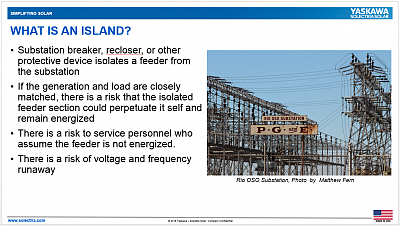
Nothing Fun About These Islands
In this discussion an island is defined as a scenario where you have PV connected to a feeder and something happens on that feeder, such as a fault, that causes the substation breaker to open. That feeder can continue to stay energized if the load matches the remaining generation. Since PV inverters are looking for a voltage source and the voltage is present, the load will absorb current from the inverters, creating voltage across it, perpetuating a situation where, in theory, everything will run forever, making a safety and reliability concern across the grid. If there isn’t anti-islanding protection, PV inverters could perpetuate energization across that line. If that happens, there is a potential risk to equipment if the voltage and frequency run away.
Anti-islanding Solutions
According to IEEE 1547 section 4, an Area EPS must be de-energized within two seconds of the formation of an island. In other words, for an unintentional island in which the PV Plant energizes a portion of the grid through the interconnection point, the PV Plant interconnection system shall detect the island and cease to energize the grid within two seconds of the formation of an island.
We have two methods for ensuring that happens. We have a passive method that monitors the voltage and frequency. Secondly we have an active anti-islanding method where we vary the output of the reactive power to help destablize the island and accelerate the dissolving of the system to extinguish the island.
Passive Anti-islanding Protection: A Numbers Game
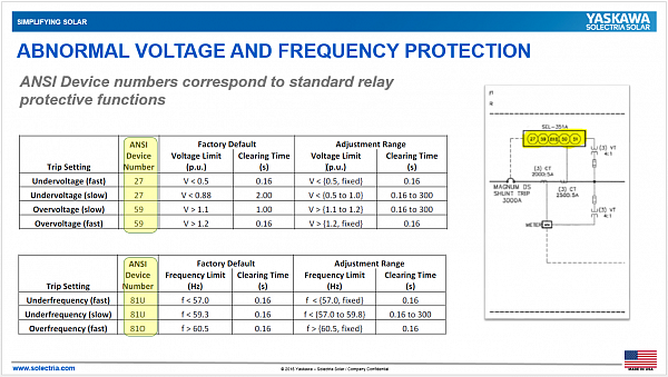
To support the passive method, we provide the voltage and frequency settings of our equipment. Every PV inverter that rolls off of the factory floor is tested for proper operation of these functions. Customers are welcome to request the test report from us for their inverter. In the event of an island, these settings will generally trip first before the active anti-islanding trips. If loads are not closely matched, but could quickly exceed their acceptable ratings, the settings that are programmed into the inverter will turn off all the inverters in their required times.
Active Anti-islanding Protection: Going Up Stairs in the Dark
For the active anti-islanding function, we use a technique called Slip Mode Frequency Shift. This varies the reactive power output of the inverter. The goal of this protection method is to destabilize an islanded feeder by trying to influence the frequency. This diagram, from the IEEE 1547 testing procedure, shows how we test the anti-islanding function in the inverter.
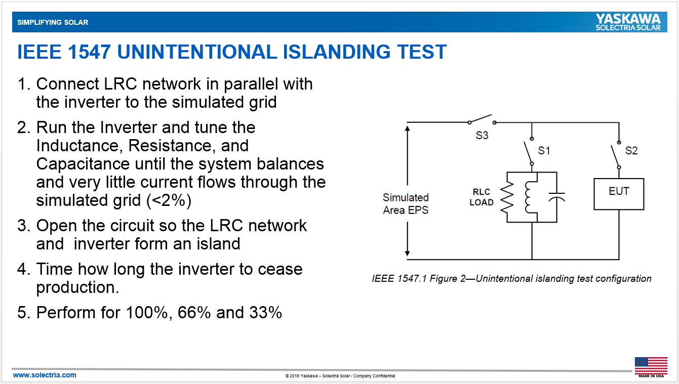
We intentionally force the frequency out of spec and push against the grid, so we can properly detect and dissolve the island. We actually turn the anti-islanding function off, create an island, turn the anti-islanding function back on, and test the ability to disturb the island within two seconds. In our tests, we actually do it much faster.
Please contact us for further details regarding our testing methodologies or if a utility would like you to conduct a risk of islanding study. A risk of islanding study is often performed when there are multiple PV inverters on a site or on a feeder or multiple generation technologies (wind, solar, and hydro) or different inverter manufacturers. This test uses software simulations to determine if additional protection is necessary. We can provide special software models of the inverter, if it is required by a utility.
Open Phase Detection: Different from PV Inverter Anti-islanding Function
If you go through a witness test, and your utility comes out to ensure voltage and frequency settings are correct, that your transformer is connected right, and that the recloser is programmed properly, they often do a test where they disconnect the whole site to make sure all the inverters turn off and a second test where they might open one phase out of three to make sure the PV inverters turn off.
In open phase detection, the inverters are looking for an imbalance of output current. We test the scenario at the terminals of our equipment, which is easy to do and to pass. The challenge is if there is a transformer between the inverters and the point of interconnection, or if you have some motors or other equipment that can interfere with the inverter’s ability to see through the transformer. So be sure to follow the transformer requirements for your equipment. A non-compliant transformer configuration will not allow the PV inverter to properly detect an open phase condition and will continue to operate. Also, activate Negative Sequence Current Protection in your relay. This will detect imbalances in the line current, and can be used to trip the recloser or breaker.
You Asked, We Answered
Yaskawa - Solectria Solar Webinars always have a lively audience with plenty of questions – and this one was no exception. Here are a few questions that Eric addressed.
Q: Where can I find the transformer requirements for the central inverters?
A: The product page for the XTM inverters on our website.
Q: Can VAR-based active anti-islanding method work in conjunction with the dynamic volt VAR control? What is the impact of ride through on anti-islanding protection?
A: We are able to implement anti-islanding for some volt VAR control. Our newest firmware allows for it. We have tested volt-VAR and anti-islanding simultaneously with no issues.
Q: Do all of your inverters have the option of Open Phase Detection
A: We do have to provide Open Phase Detection at the terminals of the inverter. If you are following the transformer spec, you should not have an issue.
Q: Will Yaskawa - Solectria Solar PV Inverters meet the NEC 2014 code for rapid shutdown within the next year?
A: That’s possible. A presentation can be downloaded from our website and is discussed on our YouTube Channel.
Q: Regarding Micro-grids – if a gen set is connected to a PV inverter wouldn’t the voltage and frequency source turn on the inverter if connected to the generator output?
A: Yes, in some cases that has happened and has been encouraged. Some customers are installing PV in parallel with generators and will disconnect from the utility and activate the transfer switch so they’re running off the diesel and supplement the energy from the diesel gen set through the solar as a way to reduce fuel costs. It is possible that there are some additional controls that need to go into place to limit the variation of the PV output and slow down the operation of the gen sets to reach equilibrium. There is a lot of study that needs to happen beforehand. Some power system simulations need to happen. Some additional protection controls need to go in to make sure the system can balance itself out, but that’s a prime example of a micro-grid.
Q: Are your transformerless string inverters basically multi-level inverters or high-frequency small magnetic converters?
A: All of our transformerless string inverters are three-level inverters (multi-level). Through the three-level IGBTs and the contactors that are built into the unit, they are able to provide sufficient isolation to meet UL 1741 requirements. It’s generally less expensive than having a high-frequency transformer.
Thank you for your interest. Please contact us if you’d like to receive webinar materials, or if you have questions.
Questions or comments? Contact:
Eric Every
Sr. Applications Engineer
Yaskawa – Solectria Solar
eric.every@solectria.com
978-771-7598
Natalie Holtgrefe
Head of Marketing
Yaskawa – Solectria Solar
natalie.holtgrefe@solectria.com
781-640-0755
Please email questions and ideas to natalie.holtgrefe@solectria.com.